· The block diagram of the closed loop system is shown below. As these systems contain feedback loop, the closed loop control systems are also called as "Feedback control systems". By giving the feedback to the input signal, we can accurately control the output of a control system. A closed loop control system can have more than one feedback loop. Examples. We use closed loop control .
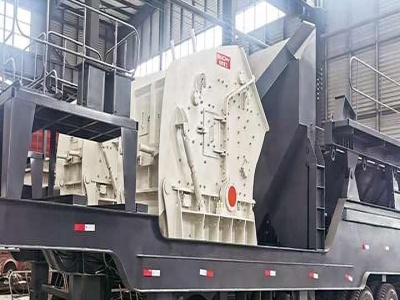
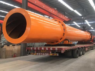
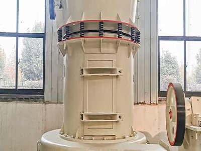
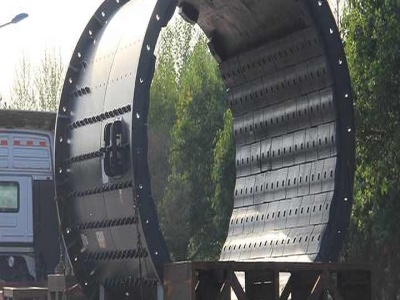
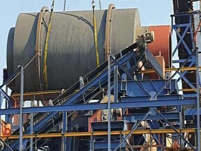
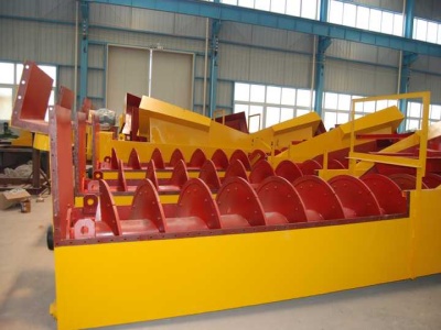
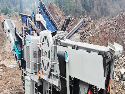
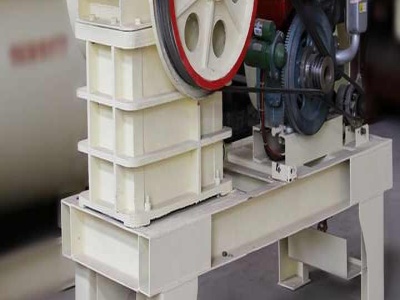
circuit diagram of coal mill mining ball mill discharge circuit diagrams coal mill model uml diagrams diagram of grinding machin coal mining in burdwan fairbanks morse model. More information; DIAGRAM OF A BALL MILL CIRCUIT YouTube. More Details: pakistancrushers/contact ballmill instumintion control circuit diagram Mining ball mill and sag ...
Enclosed here is a brief description and a circuit diagram to illustrate each type of circuit. Identify open and closed circuits. Observe each circuit diagram keenly, identify the type of circuit as open or closed and predict if the bulb would light or not based on the circuit being open (broken) or closed. Series or parallel circuit . Analyze each circuit and label it as series if the current ...
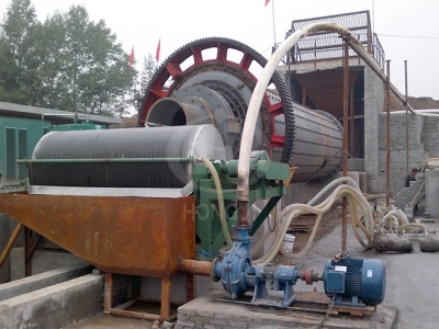
· Size distribution diagrams of closedcircuit ball mill feed and product. Full size image (B) Mineralogy of closedcircuit ball mill feed and product. Microscopic studies have been performed on ...
The questions of Portland cement clinker grinding in closed circuit ball mills. ... MnBi has high intrinsic coercivity with large positive temperature coefficient. ... Lowenergy ballmilling using specific process control agents (PCAs) was ... Drawing Sensors with BallMilled Blends of MetalOrganic Frameworks and Graphite. Get Price; electronic ear sensor for ball mill . All sensors of line ...
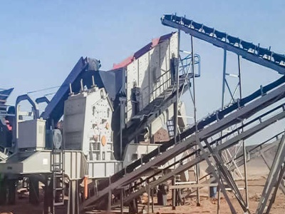
· Open Circuit Secondary and Closed Circuit Tertiary Crushing Flowsheet. Our last schematic represents a CLOSED CIRCUIT. This one involves both SECONDARY and TERTIARY crushing. This circuit is employed where either the tonnage or the work index of the ore is high enough to require that the crushing be done in stages. Again the ore will come from ...
· An electric circuit is a closed loop with a continuous flow of electric current from the power supply to the load. Here are ten simple electric circuits commonly found around the home. Electric circuits like AC lighting circuit, battery charging circuit, energy meter, switch circuit, air conditioning circuit, thermocouple circuit, DC lighting circuit, multimeter circuit, current transformer ...
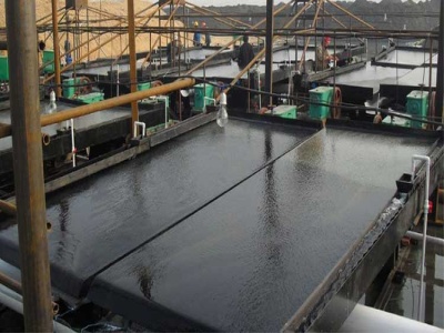
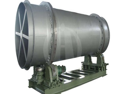
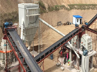
Typical mill/separator circuit. Closedcircuit systems. The efficiency of the early stages of grinding in a ball mill is much greater than that for formation of ultrafine particles, so ball mills operate most efficiently by making a coarse product, the fine fractions of this then being separated, and the coarse part being returned to the mill inlet. The proportion of the millexit material ...
· Open and Closed Circuit Diagram. Open Circuit: In an electric open circuit, no electrical connection occurs in between the source and load. If any sides of the source or other components disconnect in an electric circuit, the current will not flow. That's why the load will not be activated. Closed Circuit: In closed circuit, closed loop path occurs with the connected source and the load. For ...
You have already learnt that an electric circuit is a closed path in which a current flows. The simplest circuit has: a power source such as a cell, a conductor, and ; a load that provides resistance, such as a lamp. Cells in series. Two or more cells can be connected in series to increase the voltage in the circuit. Figure 2 below shows two cells connected in series in a circuit. The positive ...
Bulletin 1495 normally closed auxiliary contacts are required. With the motor running contacts are open; with the motor stopped contacts are closed and the pilot light is illuminated. The basic circuit and its operation is the same as the diagram on Page 6. I PUSH BUTTON STATIONS I Voltage 120V 240v 480V 60Hz 600V 60Hz Type of Station Standard Duty
· Wiring limits and home switches can be handled in a multitude of ways. But first you need to know what software you plan to use before deciding on a method. Typically limit switches have both normally open contacts (NO) and normally closed (NC) contacts. Depending on how you want to wire you can wire them in series or parallel with other switches.
· The four diodes are connected together in a closedloop bridge configuration. The following figure shows the circuit diagram of the Bridge rectifier: Circuit Diagram and Construction of Full Wave Bridge Rectifier. These diodes are arranged in series pairs that only two diodes conduct current during each half cycle. For example, during the positive half cycle of the AC input, diodes D1 and D3 ...
Circuit Drawings and Wiring Diagrams Description Successfully performing electrical work requires the ability to read and interpret many different types of drawings and diagrams. Understanding circuit symbols and components is another one of the basic building blocks needed to become an electrician. If an electrician misinterprets a drawing or diagram when wiring a house, devices could be ...
closed circuit diagram for cement mill in cement plant. close circut cement plant. design of closed circuit cement grinding system cement plant The benefits that can be achieved due to the optimisation of cement grinding system through process A 15 mio ta cement plant is having a closed circuit ball mill for cement grinding The mill has been The mill is designed to handle a total ball charge ...
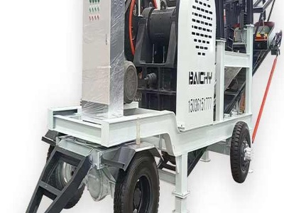
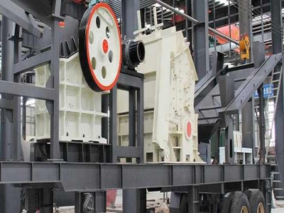
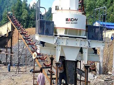
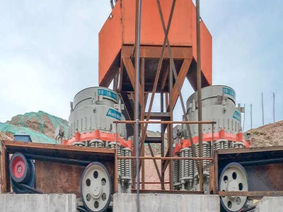
circuit diagram for ball mills and rod mill MTW Milling Machine; crusher plant 120 tph panel wiring diagram and ... 2016 the simplest grinding circuit consists of a ball or rod mill in closed circuit with a 25... AMIT 135: Lesson 6 Grinding Circuit – Mining Mill Operator ... SAG Mill Circuit Example — Gold Processing ... A diagram of types of rod mills image: 13566 ... Images of a ...
Easy to Build CNC Mill Stepper Motor and Driver Circuits: This is a follow up to the Easy to Build Desk Top 3 Axis CNC Milling Machine Once you get the machine all put together its time to make it go. So it's time to drive the motors. And here I've put together a circuit that I think is the absolu.
Fluid Transport A ball mill is running in closed circuit with a hydrocyclone pack as shown in the diagram below. The feed slurry to the cyclones has a density of 1200 kg/mº, a viscosity of and a flowrate of 50 m3/hr. The cyclone pack is loed 15 metres above the pump and is connected to the pump by 25 metres of Schedule 40 structural steel pipe. Minor losses are equivalent to 100 ...
· Open circuit. Closed circuit. It is not a closed and continuous path. It is a closed and continuous path. Electric current doesn't flow in an open circuit. Electric current flows in a closed circuit. The key in an open circuit is shown as ( ) The key in a closed circuit is shown as (.)
Overview of SeriesParallel Circuits A seriesparallel circuit, or combination circuit, combines both series and parallel connections. Most electronic circuits fall into this egory. Seriesparallel circuits are typically used when different voltage and current values are required from the same voltage source. Series components form a series ...
Fluid Transport A ball mill is running in closed circuit with a hydrocyclone pack as shown in the diagram below. The feed slurry to the cyclones has a density of 1200 kg/mº, a viscosity of and a flowrate of 50 m3/hr. The cyclone pack is loed 15 metres above the pump and is connected to the pump by 25 metres of Schedule 40 structural steel pipe. Minor losses are equivalent to 100 ...